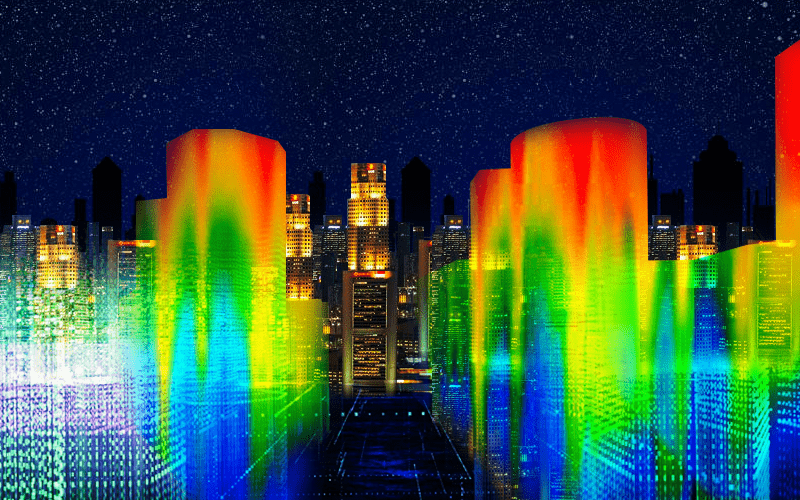
Ventilation by natural means driven by wind or mechanical means
Thermal comfort levels may be achieved using natural ventilation means driven by wind or mechanical means using HVAC systems.
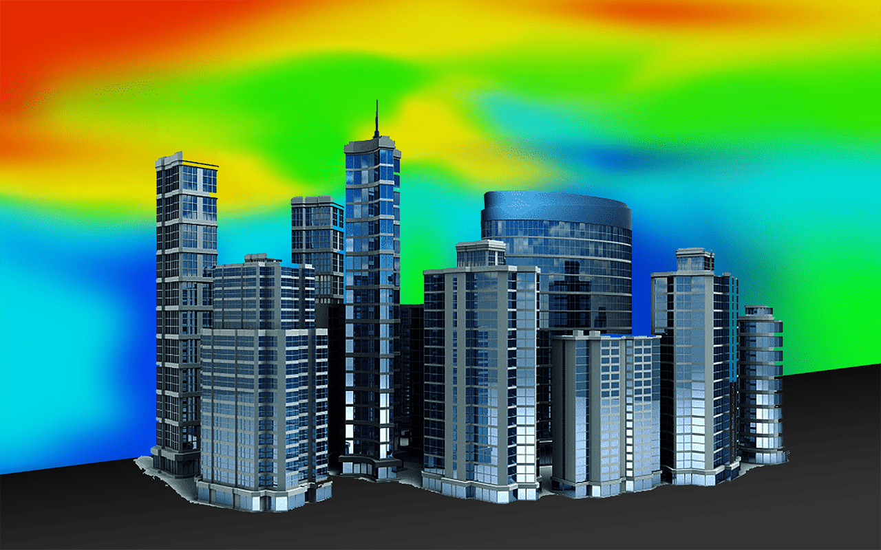
Coupled with good engineering knowledge and judgement to set up the appropriate parameters such as building porosity and wind conditions, CFD techniques can be used to provide the most innovative and rational approach to derive a natural ventilation design to achieve thermal comfort.
Performance-based ventilation designs using CFD modelling:
- Natural ventilation system in lieu of mechanical ventilation systems for carparks, driveways, loading & unloading bays
- Vehicular fumes & airflow velocities analysis for carpark ductless ventilation systems
- Thermal comfort for occupants using HVAC
- High plume vertical ventilation system for pollutants control and airflow
Acceptance Criteria for Thermal Comfort
Green Mark for Non-Residential Buildings NRB: 2015
| Thermal Comfort Level | Area-weighted ave. air velocity |
| Moderate | 0.2 m/s |
| Good | 0.4 m/s |
| Very Good | 0.6 m/s |
Effectiveness of Day-To-Day Natural Ventilation for Driveways
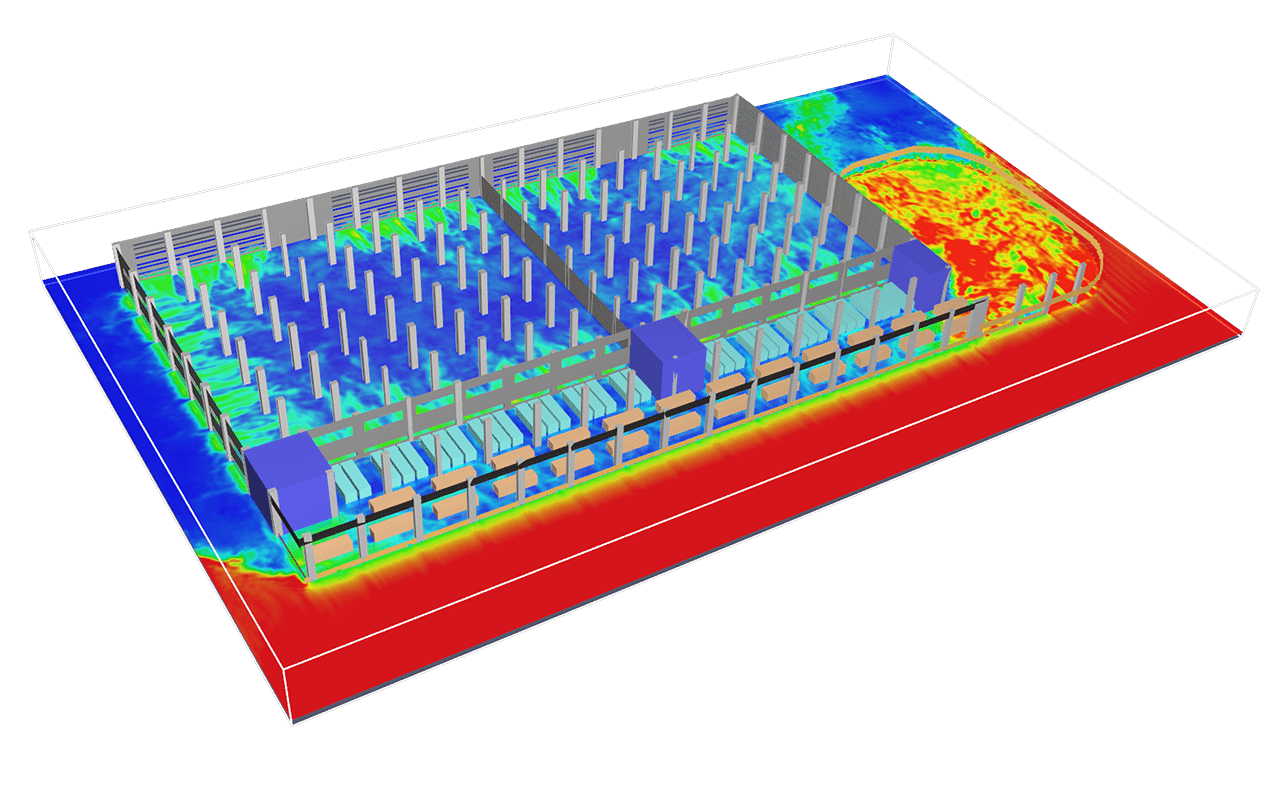
The naturally ventilated driveways, loading & unloading bays of the industrial development were remotely positioned at more than 12m away from the façade openings.
With consideration to the prevailing wind conditions and the vehicular exhaust emission levels, CFD modelling was conducted to assess the adequacy of the natural opening to ventilate and maintain safe working conditions for occupants at these remote areas.
The CFD results had concluded that safe working conditions for occupants were maintained in terms of average carbon monoxide concentration over a 1-hour period.
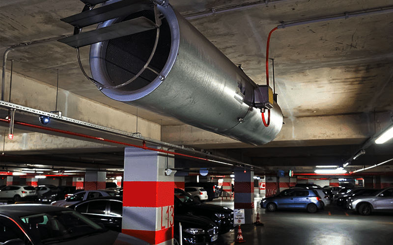
Car Park Ductless Jet Fan System
Car parks are often the place where fire incidents take place. They can reach high temperatures due to being enclosed and the high temperatures of vehicles, which can lead to disastrous fires upon oil leakage. A ductless jet fan ventilation system serves as an effective smoke ventilation system, increasing airflow velocities to eliminate excessive heat and venting away harmful smoke and vehicular fumes.
Ductless jet fan ventilation systems are powerful and only need to be installed at certain points, leaving room for other installations and improving visibility across parking decks.
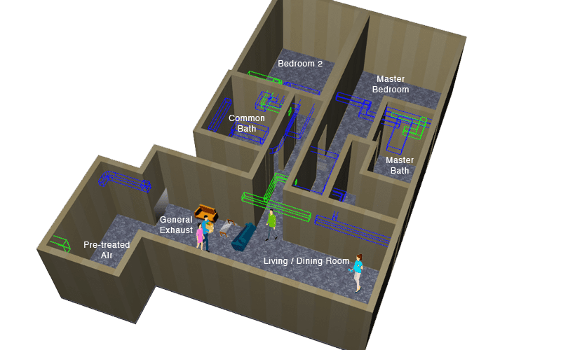
CO2 Concentration levels in a typical residential unit
According to ANSI/ASHRAE Standard 62.1-2007, CO2 concentrations in acceptable outdoor air typically range from 300 to 500 ppm.
Site measurements for the CO2 concentration in a typical residential unit were in the range from 400 to 450 ppm when no occupants are in the room.
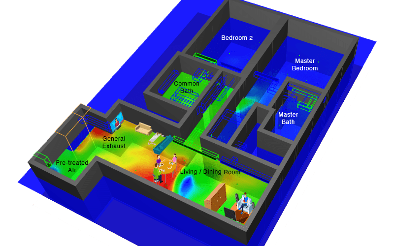
A 24-hour continuous CFD simulation was conducted for the typical residential unit to assess the effectiveness of the ventilation systems in terms of CO2 concentrations in ppm.
The residential unit for a family of 4 members consists of 2 bedrooms, a living room and 2 bathrooms.
450 ppm CO2 concentration from 8pm to 12am
(Back from school and work)
450 ppm CO2 concentration at peak value in the living, dining and common area when occupants are back in the unit after work or school.
The CFD results had concluded that the ACMV system is efficient to maintain an acceptable CO2 concentration in the residential unit.
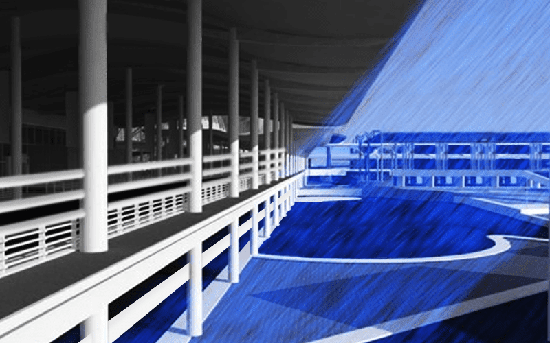
Wind Driven Rain (WDR) Simulation
The study of wind driven rain is an important design consideration in the built environment which requires good knowledge of wind speed, rain drop sizes and rainfall intensity. Wind driven rain or driving rain can significantly affect the durability of building. An example of Wind-Driven Rain (WDR) phenomenon is that parts of your apartment ruined by rain after a sudden downpour with your windows open.
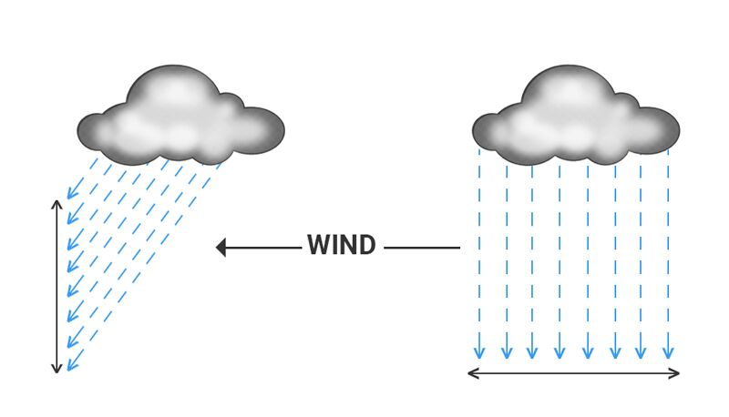
Wind-Driven Rain (WDR) Analysis is the study of the horizontal rain phenomenon when driven by wind, resulting in rain falling into naturally ventilated spaces.
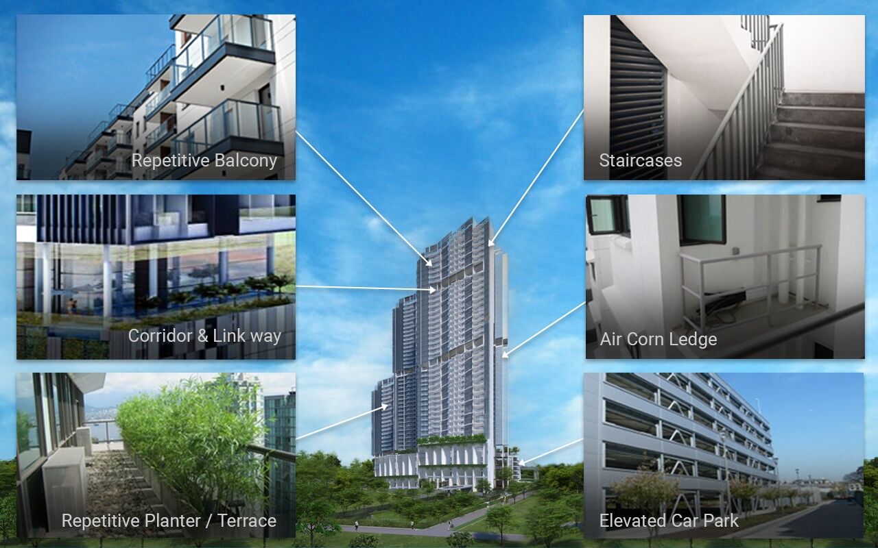
Many modern buildings are now designed with spaces for natural ventilation which whilst effectively covered are still subject to wind-driven rain. Such “Wind-Driven Rain spaces” are Aircon ledges, Balconies, Carparks, Corridors, Lobbies, Linkways, Plant Rooms, Staircases, Terraces and so on.
Wind Driven Rain (WDR) Simulation
Wind-Driven Rain (WDR) Analysis is the study of the horizontal rain phenomenon when driven by wind, resulting in rain falling into naturally ventilated spaces.









Contact Us
Follow us on: